







Heat Shrinkage Testing for DTF PET Film: Why Dimensions Matter
Learn how DTF PET film heat shrinkage is measured in MD and TD and used for dimensional stability, supplier qualification, and batch release.

Estimated reading time: 14 minutes
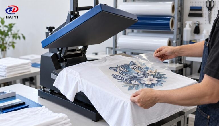
Heat shrinkage testing measures how much DTF PET film changes length and width after a defined thermal exposure. The basic method marks or measures a specimen in the machine direction and transverse direction, heats it without unintended restraint, cools it under controlled conditions, and measures the same dimensions again. Shrinkage is normally reported as a percentage for each direction.
The result matters because DTF film carries a printed image through curing and heat pressing. Even small dimensional changes can alter registration, create edge waves, change web tracking, disturb take-up, or make a printed sheet harder to position. A useful test report must state the specimen orientation, initial gauge length, oven condition, exposure time, support method, cooling procedure, measurement system, sample locations, and calculation. A number without these conditions cannot support a fair supplier comparison.
What is heat shrinkage in DTF PET film?
Heat shrinkage is a permanent dimensional change that remains after a film specimen is heated and then returned to the specified measurement condition. PET film can contain orientation and residual stresses from film manufacture, heat setting, coating, drying, slitting, and winding. Heating can release part of that stored stress and change the dimensions.
Thermal expansion during heating is not the same as residual heat shrinkage after cooling. A film can expand while hot and return close to its original size, or it can retain a smaller or larger dimension after the cycle. The test must define when the final measurement is taken. Comparing one hot measurement with one cooled measurement mixes different quantities.
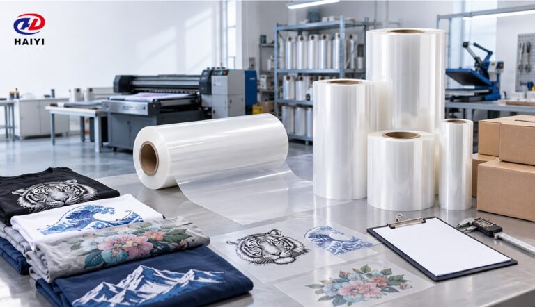
DTF film is a coated construction rather than bare PET alone. The PET base provides most of the structural support, while the ink-receiving and reverse-side treatments can influence stress balance, moisture response, friction, and curl. The overview of PET film thickness and coating quality explains this construction; the present guide focuses on measuring permanent dimensional change.
Why do machine and transverse directions matter?
Film has two principal in-plane directions. The machine direction, or MD, follows the path of the web through manufacturing. The transverse direction, or TD, runs across the web. Biaxial orientation, heat setting, coating tension, winding, and thermal history can affect these directions differently.
A single shrinkage value therefore hides important information. If MD shrinkage is larger, printed length and repeat spacing can change through the feed direction. If TD shrinkage differs across the roll, artwork width, edges, and flatness can be affected. An imbalance between MD and TD may also contribute to diagonal distortion or curl.
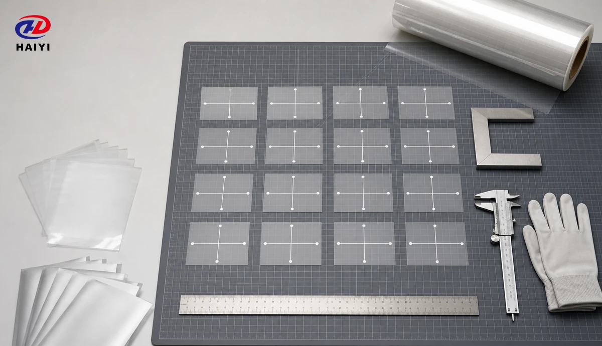
Mark MD and TD before cutting the specimen. After a small coupon is removed from a roll, visual inspection may not reveal its original orientation. Store the orientation in the sample code and on a diagram outside the active measurement lines.
How is shrinkage percentage calculated?
Use the same two reference points before and after heating. Let the initial distance be L0 and the final cooled distance be L1. A common calculation is:
Shrinkage percent = (L0 – L1) / L0 x 100
If L1 is smaller than L0, the result is positive shrinkage. If the specimen becomes longer, the equation gives a negative value. A laboratory can instead report signed dimensional change, but the sign convention must be defined. Never compare data sets until the direction and sign convention match.
Calculate MD and TD separately. Retain the unrounded initial and final measurements, then round only the reported result according to the procedure. When a specification contains a tight limit, measurement resolution and uncertainty must be suitable for the decision.
What does a simple calculation look like?
Consider a hypothetical MD gauge length of 200.00 mm before heating and 199.20 mm after cooling. The difference is 0.80 mm. Dividing 0.80 by 200.00 and multiplying by 100 gives 0.40 percent shrinkage. This example explains the arithmetic only. It is not a universal pass limit for DTF film.
Which standard methods are relevant?
ASTM D2732 covers unrestrained linear thermal shrinkage of plastic film and sheeting at selected specimen temperatures. ISO 11501 addresses dimensional change in the longitudinal and transverse directions of plastic film and sheeting after heating. The methods address the same general subject but differ in technical content, so a purchase order should name the required method and edition rather than treating the references as interchangeable.
A DTF buyer may also use a validated factory method designed around the real curing path. That can be useful for production control, but the method still needs a controlled specimen, temperature, time, support, cooling, measurement, and calculation. If the buyer and supplier use different procedures, establish a correlation before applying one acceptance limit to both.
Standards define how to measure. They do not automatically supply the correct DTF product limit. The acceptance criterion must be linked to the specific film, heat path, printer, artwork, process window, and risk.
What equipment is needed for the test?
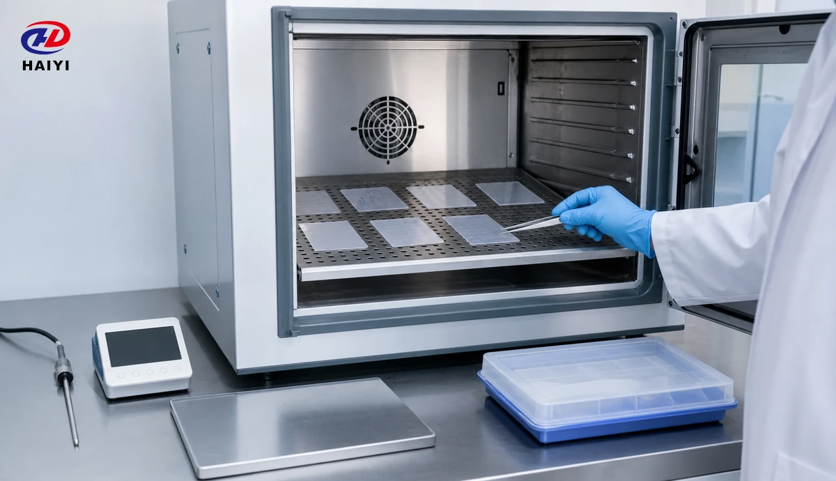
A practical laboratory setup includes a controlled oven or thermal chamber, a verified temperature sensor, a timer, heat-resistant handling tools, a specimen support defined by the method, a flat cooling area, and a dimensional measurement system. Measurement options include a calibrated ruler with suitable graduation, comparator, low-force caliper, optical system, or a purpose-built film measurement fixture.
The instrument should resolve the dimensional change that matters. A display with extra digits does not prove that the complete method is accurate. Mark width, edge definition, specimen flatness, operator alignment, and temperature stability can create more variation than the instrument display.
The oven needs adequate uniformity and recovery. A chamber control display does not prove the specimen temperature at every shelf position. Verify the working zone used for testing and avoid placing coupons near walls, doors, heaters, or airflow features unless the selected method specifies that location.
How should samples be taken from a roll?
Sampling should represent both roll width and roll length. A development study can use left, center, and right positions across the web, repeated near the beginning, middle, and end. This grid reveals edge-to-center variation, gradual machine-direction drift, and isolated anomalies. Routine batch release can use a reduced plan only after process capability supports it.
Record the batch, master roll, slit roll, web position, sample depth, front and back, MD and TD, coating state, and date. Avoid testing only the exposed outer wrap. The outer layers may have a different moisture, tension, and storage history from the roll interior.
Cut specimens cleanly without stretching, creasing, heating, or dragging a dull blade. Keep the active surface free from fingerprints, ink, powder, adhesive, and cleaning residue. If printed and unprinted specimens are compared, define ink coverage, white-ink coverage, powder, curing state, and artwork because these additions change heat absorption and stress.
How should gauge marks and initial dimensions be prepared?
Gauge marks must remain visible and stable through heating without constraining the film or changing the local surface. Use the marking method specified by the procedure. Fine reference points or lines are usually easier to measure consistently than broad marks with uncertain edges.
Place MD and TD references far enough from cut edges to reduce edge effects and far enough apart to give useful measurement sensitivity. The specimen must still fit the controlled oven zone and remain unrestrained. Use a template when repeat placement matters, and verify the template dimensions independently.
Measure each initial gauge length more than once during method development. If repeat readings vary too much, improve lighting, alignment, mark quality, operator technique, or the fixture. A poor initial measurement cannot be corrected after heating.
Why do conditioning and moisture control matter?
Temperature and humidity can influence the coating, surface stress, curl, and measurement behavior. Condition comparison samples together under the specified atmosphere for the defined time. Let sealed rolls approach laboratory temperature before opening when condensation is possible.
Record actual laboratory conditions, not only a nominal room setting. Keep samples flat or stored in the specified manner during conditioning. Avoid clips, weights, or tight envelopes that introduce a set before the test.
Moisture-related dimensional or surface effects can be mistaken for heat shrinkage when conditioning differs. The guide to DTF film moisture control explains why storage and condensation should be managed separately from thermal stability.
A practical heat shrinkage test workflow
- Define the purpose. State whether the test supports material characterization, supplier qualification, process simulation, troubleshooting, or routine batch release.
- Freeze the method. Specify sample size, MD and TD, gauge length, conditioning, oven type, temperature, exposure time, support, cooling, measurement, calculation, sampling, and acceptance rules.
- Verify equipment. Confirm calibration or verification status, oven working-zone performance, timer function, and dimensional measurement checks.
- Select and identify coupons. Map roll positions and mark orientation outside the active gauge area.
- Condition specimens. Hold samples under the defined environment and protect them from contamination or restraint.
- Measure initial dimensions. Record each MD and TD gauge length with the approved instrument and technique.
- Expose specimens to heat. Place coupons in the defined position without unintended tension, contact, overlap, or airflow obstruction. Start timing according to the method.
- Cool consistently. Remove specimens safely and allow them to reach the defined final measurement condition without flattening or stretching them.
- Measure final dimensions. Use the same reference points, instrument, orientation, and operator method where practical.
- Calculate and review. Report MD and TD values, specimen observations, invalid tests, location patterns, and the batch decision.
How should thermal exposure conditions be selected?
Test conditions should represent the decision. A characterization study may measure several temperatures to show where shrinkage begins to accelerate. Routine quality control can then use one selected condition that is sensitive to process drift. A production simulation may use the actual oven path, but it should not be called equivalent to a standard method without evidence.
Temperature and time work together. A higher temperature for a short interval does not necessarily produce the same result as a lower temperature for a longer interval. Air velocity, radiant energy, tray material, specimen mass, oven loading, and recovery after opening can also change the heat delivered to the coupon.
Do not copy a curing or pressing setting from a general article and treat it as a laboratory shrinkage condition. The existing guide about excessive DTF curing temperature covers process failure symptoms. A dimensional test needs a separate controlled exposure selected for measurement sensitivity and product use.
What does unrestrained exposure mean?
Unrestrained exposure allows a specimen to change dimensions without tension or clamping that suppresses movement. The support must keep the coupon in the defined test position while avoiding adhesion, friction, overlap, edge trapping, or air pressure that changes shrinkage.
A specimen hanging under its own weight is not necessarily unrestrained in the same way as a flat specimen. A film placed on a high-friction tray may also be partly restrained. Use the support arrangement required by the selected method and document any deviation.
Real DTF production is often restrained by web tension, rollers, ink, powder, take-up, or a heat press. That is why an unrestrained laboratory result and a process simulation answer different questions. The laboratory test characterizes material tendency. The process test shows behavior in a particular machine path.
How should cooling and final measurement be controlled?
Measure after the specimen reaches the defined condition. Hot film may still change size, and a warm coupon can be difficult to place consistently. Cooling time, surface, airflow, and orientation should remain the same for every sample.
Do not flatten curl with heavy plates unless the method specifically defines that action. Flattening can impose strain and hide a functional problem. If a low-force transparent cover or optical technique is used for measurement, validate that it does not change the gauge distance.
Record curl, waves, buckling, blocking, haze, coating transfer, odor, or visible damage separately from linear shrinkage. A specimen can have acceptable gauge-length change but unacceptable flatness. Conversely, curl can occur because opposite surfaces develop different stress even when average dimensions change little.
How can measurement error be reduced?
Use the same reference points before and after exposure. Keep the specimen aligned with the measurement axis. A slight angular error can make the measured distance longer. Optical systems should use controlled lighting, focus, magnification, calibration, and edge-detection settings.
Evaluate repeatability by letting one operator measure the same stable coupons several times. Evaluate reproducibility across operators, days, instruments, and oven positions. Randomize samples so expectation does not influence the reading. Use coded specimens when supplier identity could bias interpretation.
If measurement variation consumes most of the proposed tolerance, do not tighten acceptance limits. Improve specimen preparation, gauge marks, fixture, oven uniformity, cooling, or training first. A supplier rejection requires a method capable of distinguishing real product variation from test noise.
How should results be analyzed across a batch?
Report every MD and TD result, not only the average. Calculate location means, range, and any agreed variability statistic. Averages can hide a high-shrinkage edge or a beginning-to-end trend. Map results by roll position so the pattern remains visible.
Compare the heat-shrinkage map with process data such as PET lot, coating run, oven zone, line speed, winding tension, slit position, and storage history. A cross-web pattern may point to heat-setting or coating differences. A machine-direction drift may align with process startup, temperature recovery, or tension changes. These are investigation hypotheses, not automatic root-cause conclusions.
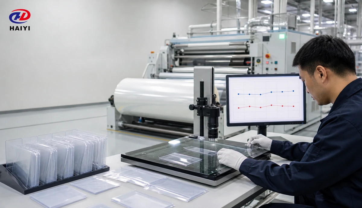
Heat shrinkage should also be reviewed beside thickness and coating distribution. The DTF film thickness guide explains why a thicker film is not automatically more dimensionally stable. The coating weight and uniformity method provides a separate map for coating process control.
How should acceptance criteria be created?
There is no universal heat-shrinkage limit for every DTF film. Build criteria from an approved product and process. Test several batches that perform well on the intended equipment, quantify normal MD and TD variation, challenge the relevant heat window, and link results to registration, flatness, feeding, curing, pressing, and release.
A complete specification can include separate MD and TD limits, a maximum direction imbalance, a within-roll spread rule, sample count, retest procedure, invalid-test rules, and functional confirmation. Set the decision band with measurement capability in mind. Retest rules should be defined before a failure and should not permit unlimited testing until a convenient result appears.
Use change control. A new PET source, gauge, orientation process, heat-setting condition, coating formula, drying profile, winding method, or manufacturing line may require requalification. The DTF film supplier audit checklist helps buyers verify how specifications, testing, traceability, and process changes are managed.
Why should laboratory results be linked to functional trials?
A coupon test does not reproduce every force in printing. Run a controlled trial through the intended printer, powder shaker, curing unit, take-up, cutting, heat press, and peel sequence. Keep artwork, ink load, powder, speed, temperature, dwell, pressure, fabric, and environment consistent.
Measure printed reference distances before and after the relevant heat stages when registration matters. Observe edge waves, diagonal distortion, web drift, head-strike risk, take-up alignment, sheet positioning, and transfer placement. Functional results show whether a laboratory limit predicts a business-relevant outcome.
Do not combine unrelated defects into one heat-shrinkage diagnosis. Release force, coating behavior, static control, moisture, ink load, and equipment calibration can create similar symptoms. The DTF film release-force testing guide and the DTF film surface-resistance test cover two separate quality dimensions.
Common test mistakes and corrective actions
| Mistake | Why the result is weak | Corrective action |
|---|---|---|
| Orientation is not marked | MD and TD data can be reversed | Mark web directions before cutting |
| Only one coupon is tested | Roll variation remains invisible | Use a mapped, risk-based sample plan |
| Oven setpoint is treated as specimen temperature | Working-zone variation is ignored | Verify the actual test zone and loading |
| Specimen is clamped or dragged | Restraint changes dimensional movement | Use the defined low-friction support |
| Final size is measured while warm | Thermal expansion and residual change are mixed | Cool to the specified condition |
| Curl is flattened by force | The test can hide a functional defect | Use a validated low-force or optical method |
| Only an average is reported | Directional and positional patterns disappear | Report MD, TD, spread, and sample map |
| One generic limit is copied | Condition and application may not match | Build product-specific criteria from evidence |
What should appear on a heat-shrinkage report?
- Product, batch, master roll, slit roll, and sample location.
- Front and back identification plus MD and TD orientation.
- Referenced standard or controlled internal procedure and revision.
- Specimen size, gauge marks, initial dimensions, and measurement device.
- Conditioning time, temperature, humidity, and storage condition.
- Oven type, verified working zone, setpoint, actual observation, and exposure time.
- Specimen support, loading pattern, cooling method, and final measurement timing.
- Final dimensions, calculation, sign convention, MD and TD percentages, and observations.
- Acceptance limits, measurement validity, retest record, and batch decision.
- Operator, equipment identity, calibration status, deviations, and approval.
Trend reports are more useful than isolated certificates. Review MD and TD medians, ranges, direction imbalance, edge profiles, and batch shifts. Retain representative samples so later customer reports can be compared with original production evidence.
Frequently asked questions
Is heat shrinkage the same as curl?
No. Heat shrinkage is a measured in-plane dimensional change. Curl is an out-of-plane shape change that can result from stress imbalance between layers or directions. Record both when they affect use.
Does thicker DTF film always shrink less?
No. Thickness affects stiffness and handling, but orientation, heat setting, residual stress, coating, temperature, and manufacturing history also control shrinkage.
Can a heat press be used instead of an oven?
A heat press can support a process simulation, but pressure, platen contact, release paper, and restraint make it different from an unrestrained oven method. Keep separate procedures and limits unless correlation is proven.
Should printed or unprinted film be tested?
Unprinted film is useful for incoming material and batch control. Printed specimens help evaluate the actual process. State ink, powder, coverage, curing, and artwork when testing printed film.
How often should heat shrinkage be tested?
Frequency should follow risk and process capability. Qualification, material or process changes, unusual trends, and customer complaints usually justify more testing than a stable routine process.
Develop a wholesale or custom DTF film specification with Haiyi
Haiyi supplies DTF film for wholesale, distributor, importer, printing-supply, private-label, OEM, and custom requirements. A productive B2B program can define PET construction, roll width and length, coating, peel behavior, anti-static performance, heat-shrinkage method, packaging, sampling, and batch documentation as one controlled specification.
Share the printer platform, curing equipment, temperature window, web speed, artwork dimensions, ink coverage, roll format, destination climate, monthly demand, and any current curl or registration evidence. Haiyi can use that information to discuss suitable samples and a qualification plan. Product information and contact options are available throughout the Haiyi website.
Begin with controlled sample trials and an agreed report format before scaling volume. This approach lets buyers compare batches using reproducible dimensions rather than relying on appearance alone, while giving the supplier clear data for process control and continuous improvement.